Scientific Sector
ICAR/01 Hydraulics
Number of University Credits
12
Educational Goals
The course deals with fundamental issues of the second degree class of Civil Engineering, of which is an essential and distinctive educational activity. The teaching of hydraulic measurements and models and Hydraulics II provides students with the necessary information and details on hydraulic measurements and basics of physical hydraulic modeling models and pipe networks and open-channel flows. The program is divided into two modules. In the first module the course aims to address the topics of hydraulic measurements and the fundamentals of physical hydraulic modeling, with the principles of the dimensional analysis, the geometric, kinematic and dynamic similarity. In the second module students are given the skills necessary for understanding the fluid dynamics of currents in ducts, through the solution of the typical problems of steady or unsteady flows. Furthermore, the open-channel topics are presented and typical problems are solved, with the analysis of the gradually varied flow profiles and the unsteady flow.
Summary of the program
I module: Hydraulic measurements and models
Hydraulic measurements
Measurement of velocity and discharge by conventional current meter methods.
Measurement of velocity and discharge with acoustic and electromagnetic methods.
Uncertainty of measurements. Data analysis in time and frequency domains.
Physical Hydraulic Modeling
Basics. Dimensional analysis and Pi theorem.
Geometric, kinematic and dynamic similarity.
Principles of the physical model construction.
II module: Hydraulics II
Viscous Flow in Ducts
Steady flows in ducts.
Pipe network: typical design and check problems.
Unsteady flows in ducts.
Open-Channel Flows
Gradually varied flows.
Unsteady flows.
Preparatory exams
See your academic year regulations.
Lab training requirements
The activities of lab training are required, since they are fundamental also the theoretical part of the course.
Final examination
The final exam is composed of oral test and exercises.
Detailed program of the course
I module: Hydraulic measurements and models
Hydraulic measurements
Concept of measures. Measurement errors. Types of errors. Propagation of errors (sum, difference, product and power). Measuring chain (sensors, transducers and their characteristics). Analog to digital conversion of signals. The problems related to the sampling, acquisition time and frequency acquisition of signals. Nyquist frequency. FFT (Fast Fourier Transform). Exercise on the FFT. Remote transmission of the measures.
Level and pressure measurements. Gauge height measurements. Gauge with signal integrator. Measuring system of the percentage of air present in the water. Liquid level floats. Bubble gauge. Resistance wave gauge. Ultrasound gauge.
Velocimeters. Laser Doppler Velocimetry (LDV). The Doppler effects. Case a) The source moves relative to the medium and the observer is still. Case b) The source is still and the observer moves relative to the medium. Case c) The source and the observer are moving. How LDV works. LDV characteristics.
Acoustic Doppler Velocimetry (ADV). Acoustic Doppler Velocity Profiler (ADCP).
Flow meters. Weirs. The measuring conditions defined by the standard EBN ISO. Calibration of a weir. The principle used in metrology for gauges calibrated for differential pressures. Venturi tubes, long and short-form. Flow nozzles. Orifices. Calibration of a Venturi tube. Curves of the coefficient k of a Venturi tube.
Ultrasonic flowmeters based on the Doppler effect. Flight time ultrasonic flowmeter. Main characteristics. Versions flow-tube and clamp-on.
Electromagnetic flowmeters. Rotameters.
Physical models in Hydraulics
Physical models in Hydraulics. Field monitoring, physical models and mathematical models. Strengths and weaknesses. Typical scales of length and time of the engineering problems. Geometric, kinematic and dynamic similarity. Dimensional analysis applied to physical modeling. Interpretation of the numbers of Reynolds and Froude. Example of a physical model that requires both the analogy of Reynolds and Froude. Scale effects.
II module: Hydraulics II
Typical problems of long pipes. Analysis of the possible methods to increase the flow in ducts (parallel conduits; use of a pump). Conduits with pumps. Limit position of a pump. Limit flow rate with the use of a pump. Pumps under positive suction head. Pumps with negative suction pressure.
Design of pipelines with an increase of the flow rate with use of a pump. Use and resolution of the Colebrook equation for the design of commercial ducts. Using Mathematica software for the solution of nonlinear systems.
Hydraulic disconnection of a water network. Problems of design and control of open pipeline systems. Exercises on water networks. Problem of new and old conduits (with the increase of the pipe roughness). Effect of roughness and control of the flow rate in new pipes. Minor losses in pipe systems. Exercises (also with the aid to the computer) on the minor losses in pipe systems.
Hydraulic management of open pipe systems. Exercise on the control of a pipe systems assuming the closure of some gates. Exercise on the control of a pipe system with a uniformly distributed flow rate.
Unsteady flow in ducts. Water hammer celerity. Wave phenomena. Other examples of unsteady flows in ducts. Case in which no free surface is present, the liquid can be considered as incompressible and the duct non-deformable. Case in which no free surface is present, the elastic properties of the liquid and duct must be considered and the flow head loss can be neglected. Case in which a free surface is present, the elastic properties of the liquid and duct can be neglected, but the flow head loss must be considered.
Analysis of the high penstocks of the hydroelectric installations: tunnels and high penstock.
Oscillations of a liquid column in a U tube. Case of inviscid liquid. Case of a laminar flow of a Newtonian fluid. Case of turbulent flow of a Newtonian fluid. Using Mathematica for solving cases of Newtonian liquids.
Channels. Hydraulic grade line and energy grade line. Definition of specific energy, the energy diagram as a function of the water height; diagram of the water height in a channel section as a function of discharge per unit width; hydraulic radius: the case of a large rectangular section; steep and mild sloped channels.
Gradually varied flow profiles in steep and mild sloped channels. Hydraulic jump. Proof of the equation of the conjugate depths of a hydraulic jump. Energy loss in a hydraulic jump. Gradually varied flow profiles downstream of a gate. Gradually varied flow through bridge piers or over a bump. Using Mathematica software for the gradually varied flow profiles. Celerity of small perturbations in channels. Absolute and relative celerity in steep and mild sloped channels. Exercises on the gradually varied flow profiles. Finite difference method applied to the gradually varied flow profiles.
Composite channel sections. Main channel and floodways. Marchi’s formula for the design and control of channel cross sections. Relative roughness coefficient and shape coefficient of the channel cross section. Exercises on transition turbulent flow conditions in channels. Computer use for the resolution of the exercises.
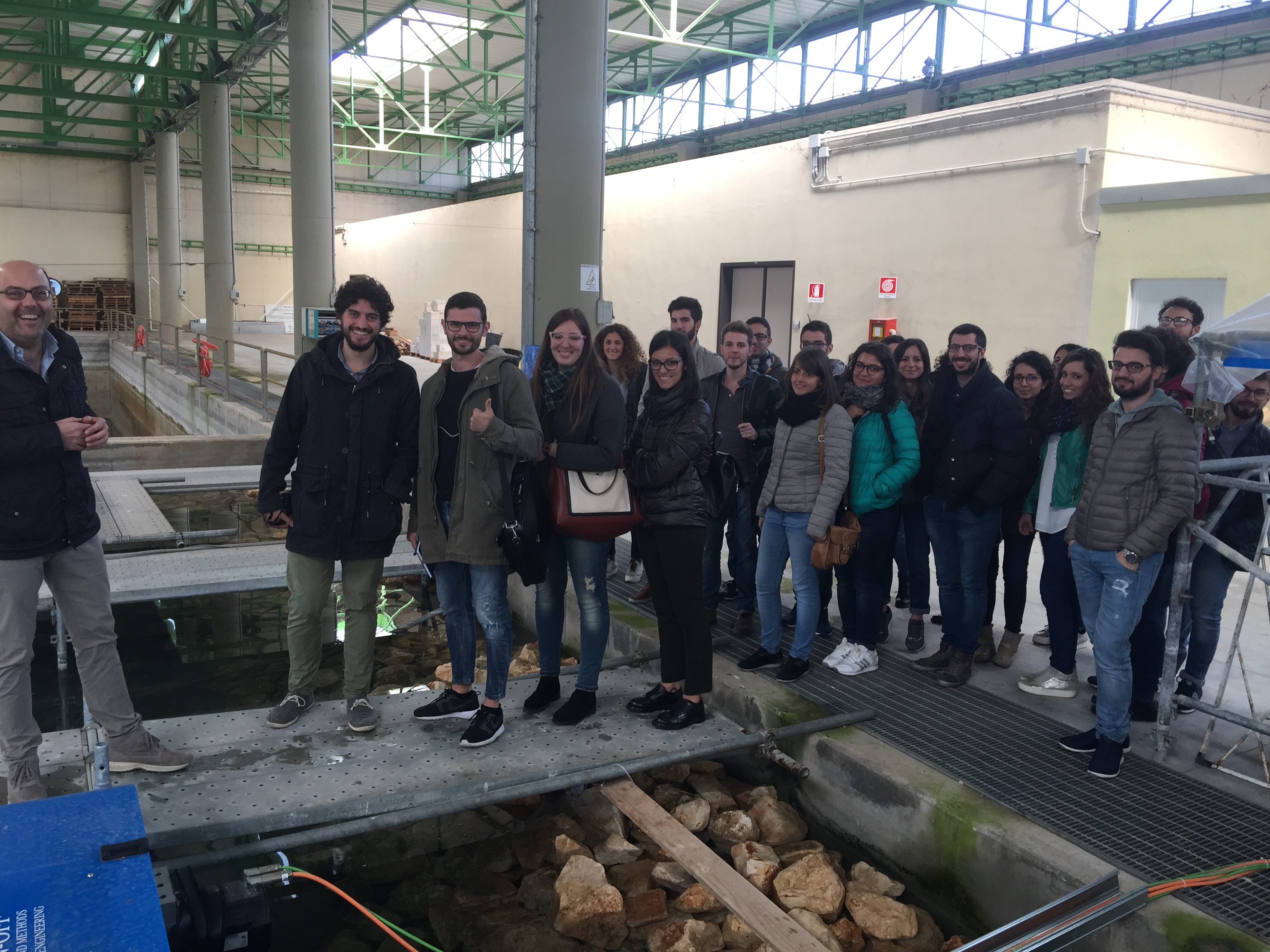
Lab training
Technical visit of the Coastal Engineering Laboratory. Analysis of the laboratory. Analysis of a channel with a very high aspect ratio. rectangular section with its buoyant jet thermal-hydraulic system. Analysis of the physical model of the Port of Melendugno. Analysis of the two-dimensional wave channel, with the following measurements: LDV, ADV, ultrasonic height gauge, electromagnetic flowmeters.
Technical visit of the Hydraulics and Hydraulic Construction Laboratory of Bari. Calibration of a Venturi tube.
Books
M. Mossa, A.F. Petrillo, 2013, Idraulica, Casa Editrice Ambrosiana, Milano, ISBN: 978-8808-18072-8.
S. Longo & M. Petti, 2004, Misure e Controlli Idraulici, Mc Graw-Hill.
G. Pulci Doria, 1992, Metodologie moderne di misure idrauliche e idrodinamiche, CUEN, Napoli, ISBN 88 7146 183-5.
A. Adami, 1994, I modelli fisici nell’Idraulica, CLEUP Ed., ISBN 88-7178-361-1.
F.M. White, Fluid Mechanics, McGraw-Hill, 4th edition, 1999.
WMO (World Meteorological Organization), Manual of Stream Gauging, Vol. I and II, 2010.


